A guide to digitizing film.
2026
The motivation
I have bought a flatbed scanner. It's marketed resolution was 3000dpi, which would be enough to make 10k pixels scans from my 120 film. The scanner produces 16-bit TIF files.
Anyways the real resolution is far from what it is marketed as. The scanner is producing bloated files with duplicate pixels. Out of 16 megapixels only 2 megapixels contain actual information due to aliasing. Yes, it truly has 16-bit color space though. All the reasonably priced scanners actually cap around 2000 dpi. But it is this terrible bit depth utilization, which makes my unit inferior to other solutions.
Also I want an option to do wet mount scanning, scan 120 or 35mm films and switch between them easily, scan with hard or soft light to either get prominent grain or smooth out scratches and dust. And at this point I have decided to build it. And the best way to understand something is to try and teach it.
The theory
To describe why I build the scanner and it's workflow a particular way, I first need to eplain the not very simple theory behind it. Let's talk about luminosity first, then add color on top of that.
- Luminosity
Scanning a film is a form of a measurement. In any measurement we can define two key factors. First is replicability and consistency - if one follows the instructions, they should be able arrive to exactly the same result. Second is signal to noise ratio - when we talk about SNR in photography, we mean how many pixels are attributed to random noise out of all of the pixels. But with aliasing of the scanner we encountered different problem, duplicate pixels.
Hence we need to rather talk about ENOB (Effective Number Of Bits). The ENOB is a term usually attributed to analog to digital converters, it describes the effective resolution of a real converter in terms of the number of bits an ideal converter with the same resolution would have.
Hence we need to rather talk about ENOB (Effective Number Of Bits). The ENOB is a term usually attributed to analog to digital converters, it describes the effective resolution of a real converter in terms of the number of bits an ideal converter with the same resolution would have.
In a linear sensor readout ENOB provides a link between bit depth and dynamic range (DR), where 1 stop of noise-free DR corresponds to 1 bit of data depth.
- I. Gamma
Gamma can be thought of as any curve mapping input luminance to output luminance on a logarithmic scale. In a film it is the characteristic curve mapping scene dynamic range to density, in digital imaging it maps scene dynamic range (in our case the density) to dynamic range of the n-bit color splace. Then our monitor maps this n-bit color space to brightness again.
By the time we see the file on the monitor, the density we actually measured went through two gamma adjustments. Here comes the importance of using gamma 1.0, which is a 45 degree slope mapping the input to output luminance in 1:1 relation, preserving the original film gamma.
Now this curve for digital files could mathematically be guessed as N = P•k, where N is the digital number, k is the gain (ISO) and P is the number of photons hitting the sensor.
When we apply gamma to the equation, we need to think about it as an exponent used to map light values. Hence the number of photons has to be raised to gamma (γ): N = Pγ • k
But any time we deal with gamma, the relationship is logarithmic to preserve equal spacing between stops. So we get log (N) = γ • log (P) + log (k)
This is the form of a linear equation: y = mx + b
For gamma 1.0 the slope (m) of this line is determined entirely by γ = 1, which represents the 45 degree line. The y-intercept is determined by log(k), then if you raise the gain (k) by one stop, k becomes 2k. The slope remains exactly 45 degrees and the whole curve is shifted along the y-axis. Preserving the slope of the gamma curve even if ISO changes.
Anyways guaranteeing a perfect gamma 1.0 workflow is practically impossible, for instance we do not know what the ADC does, some of it's quirks could then be compensated by the RAW inscription. Getting information on how the RAW is made from the camera sellers is unlikely due to the companies secrets.
The result is likely linear gamma 1.0, but it is not set in stone, it is most likely a straight-ish 45 degree-ish line, which shape will likely suffer with raising noise - ISO.
- II. File type
The first step in the scanning process is to determine how we store the information. For this workflow it is crucial to use a file supporting gamma 1.0. For instance RAW is using it. The need for linearity is in order to have 1:1 correspondence between the dynamic range and luminosity values, which allows us to use ENOB and later, to do exposure stacking consistently.
In a standard RAW file linearity is not guaranteed due to the random noise, mostly in the deepest shadows, we will lend a denoising method from astrophotography to achieve almost 100% signal and hence the better linearity of the file.
- III. Digitizing paradox
Film negative is famous for it's rendition in highlights, digital for it's shadow recovery. At first glance they should complement each other, but they do not.
The linear gamma scanning has an unwanted side effect - half of all the bits are contained in the brightest stop. The thinnest parts of the negative (scene shadows) fall into the brightest stop of the digital scan monopolizing 50% of the available data values. Conversely the densest parts (scene highlights) are attributed with the darkest stops of the digital scan, where linear encoding allocates exponentially less data to each stop, risking banding. Hence exposure stacking is a necessity even with sensors operating in 16-bit
To prevent banding visible to human eye we need to rely on Weber's Law, which says we can generally detect a distinct band if the difference in luminance between two shades is greater than 1%. Hence to render a banding-free gradient across 100 px we need at least 100 tones. When we convert this law to stops, we have to ask how many 1% steps does it take to double the light, the answer is approximately 69.6. Hence you need at least 70 tones to prevent banding between stops regardless of how many pixels the image has.
Here is a tone allocation of 12-bit file.
Stop 1: 2048
Stop 2: 1024
Stop 3: 512
Stop 4: 256
Stop 5: 128
Stop 6: 64
Stop 7: 32
Stop 8: 16
Stop 9: 8
Stop 10: 4
Stop 11: 2
Stop 12: 1
Stop 1: 2048
Stop 2: 1024
Stop 3: 512
Stop 4: 256
Stop 5: 128
Stop 6: 64
Stop 7: 32
Stop 8: 16
Stop 9: 8
Stop 10: 4
Stop 11: 2
Stop 12: 1
This means anything below stop 5, which with negative is the bright part of the image, might be a subject to banding.
Here is a tone allocation of 16-bit file.
Stop 1: 32768
Stop 2: 16384
Stop 3: 8192
Stop 4: 4096
Stop 5: 2048
Stop 6: 1024
Stop 7: 512
Stop 8: 256
Stop 9: 128
Stop 10: 64
Stop 11:32
Stop 12: 16
Stop 13: 8
Stop 14: 4
Stop 15: 2
Stop 16:1
Stop 1: 32768
Stop 2: 16384
Stop 3: 8192
Stop 4: 4096
Stop 5: 2048
Stop 6: 1024
Stop 7: 512
Stop 8: 256
Stop 9: 128
Stop 10: 64
Stop 11:32
Stop 12: 16
Stop 13: 8
Stop 14: 4
Stop 15: 2
Stop 16:1
The benefit of using a 16-bit sensor is now obvious.
- IV. Determining dynamic range (DR)
We have to determine how large the color space needs to be, so we capture all the information. The first step is then determining the density and hence dynamic range of our transparency. We can either guess it via the characteristic curve of each film, where the horizontal axis represents exposure, usually plotted as log10 E (or Log Exposure) and horizontal axis represents the density log10D. Because it operates on Base 10, every time you double the light (which is exactly 1 stop), the log value increases by approximately 0.3 (since log102 = 0.301)
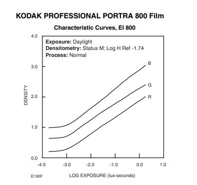
For this film, there are approx 4 usable log exposure steps under lab conditions, then 4/0.3 = 13.3 stops of light of the scene was mapped to 3 log density steps, then 3/0.3 = 10
Here we can see the non-linearity of film gamma in practice.
To determine needed DR what we need to measure is not the scene the film captured, but what the film contains in density. Hence for this film we need at least 10 stops.
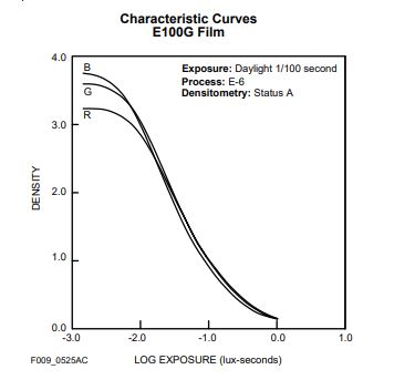
We need to optimize the workflow for at least the densest films we then probably encounter, which are color slide films with almost 4 logD steps, hence 13 stops.
Anyways this is only theoretical density under lab conditions. It can be lower or higher depending on the scene and development process. Hence you should use a densitometer for accurate evaluation.
- V. Choosing the bit-depth
Now when we know the DR, we know if we will have to do exposure stacking with our current equipment. Thanks to the 1:1 correspondence between dynamic range and luminosity levels we know, that 8-bit file will contain (28 = 256) 8 stops of DR. 12-bit file will contain 12 stops etc. The only exception is a floating point workspace, like 32-bit in photoshop, which no longer is using integers to store the values, but 32-bit floats, you can represent numbers as small as 1.18 x 10-38 giving us over 120 stops of DR.
- VI. Choosing the HDR threshold
Because of the digitizing paradox and human eye sensitivity to rather highlights than shadows, we need to choose the best way to optimize for our sensor to prevent banding in the highlights after inversion by making sure each stop has allocated enough bits. Now depending on what sensor we use, this treshold is either anything below 6.25% gray for 12-bit, or 0.19% gray for 16-bit.
Since 16-bit digital cameras are not widly affordable I will do the workflow for 12-bit, but keep in mind, their capabilities in terms of capturing dynamic range have a mathematical cieling and the workflow is more labor intensive compared to working with 16-bit.
Our maximum stop difference for HDR stacking is given by our number of usable stops, in case of 12-bit this are the first 5 stops. But in 12-bit we need to do 7 stop stacking to move stop 12 to stop 5 tone allocation. This means we need to to the HDR from at least three images.
- VII. Exposure stacking
The purpose of previous subsections was to lay a foundation to make this process repeatable and consistent.
We will then need to do three exposures, standard +0 exposure to obtain our shadows, then +4 stops exposure to obtain our lower highlights and +8 stops exposure to obtain the higher highlights. This moves even the stop 12 to stop 4 tone allocation levels to satisfy the Weber's Law of 12-bit file with a safe margin.
We then move this three 12-bit files into a 32-bit workspace supporting layers. On top we place our +0 exposure, then +4 and +8 as last, in +0 we select everything darker than stop 5 (including) and mask it or delete it. Then we decrease the exposure of the +4 layer by 4 stops. In the +4 layer we select everything darker than stop 8 and mask it and finally we decrease the exposure of +8 layer by 8 stops.
This way we obtained a 20 stops file from three 12-bit. 12 out of the 20 stops have enough tone allocation to prevent banding, and then we can either disregard the rest by saving the file in 12-bits or keep them by saving in 32-bits. Only then we should proceed with inverting the image, which again is a 1:1 operation.
In theory we could now obtain 4 more stops of sufficient tone allocation using the same method, but 16 stops of DR is where we hit the 12-bit sensor cieling, because the next stop would be 100% white.
- VIII. Noise elimination
Any digital sensor is producing inevitable noise in shadows, due to a low uniform illumination probability. This noise contributes to bloating the file and should be eliminated. To determine how much noise your sensor is outputting at different ISO settings, visit photonstophotos.net - There you will find graphs of your sensors dynamic range capabilities, or rather the ENOB. If your sensor is producing 12-bit files, but has only 10 stops worth of ENOB, then it means the bit-depth utilization is 83.3%
If the noise is perfectly random, then to eliminate this noise we can lend a technique from astral photography. If we take multiple exposures of the same scene and then for each pixel choose the average value, our ENOB improves by log2N0.5 stops. So for N = 8 frames the improvement is 1.5 stops.
If the noise is perfectly random, then to eliminate this noise we can lend a technique from astral photography. If we take multiple exposures of the same scene and then for each pixel choose the average value, our ENOB improves by log2N0.5 stops. So for N = 8 frames the improvement is 1.5 stops.
You can see this effect in this simple experiment, I have taken eight 12-bit raw pictures of the same scene, iso 25600, underexposed intentionally to add noise for demonstaration purposes. The only thing which changes between them is noise distribution.
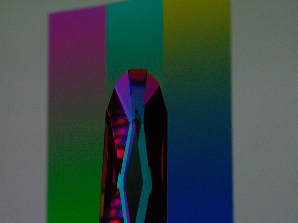
Raising the exposure makes the noise more prominent:
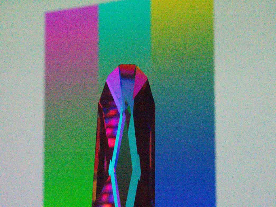
I have stacked 8 underexposed shots in 16-bit photoshop color space of the same scene and did the average, then raised the exposure by same amount:
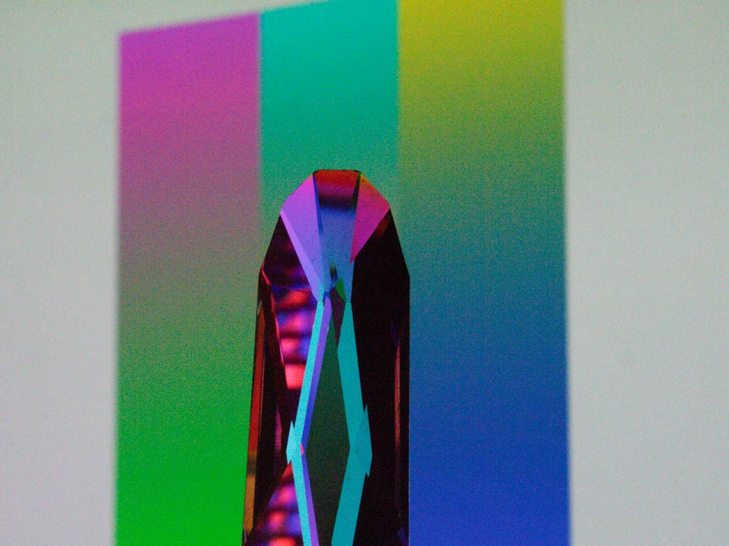
The number of distinct colors of the unstacked, uncorrected 12-bit file saved inside 16-bit tif was 3,408,974, after it was 1,777,259 due to noise reduction.
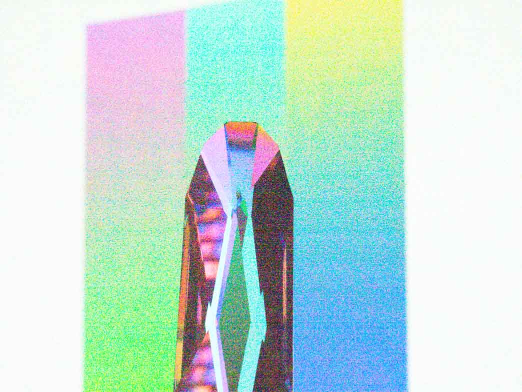
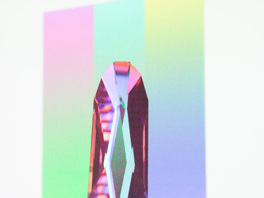
My Lumix G9 is rated at 10.3 stops ENOB at ISO 100, by adding 1.5 stops ENOB, the new bit-depth utilization ratio is 11.8 / 12 = 98.3% anyways the example was shot at iso 25600, then the ratio is around 50% after the denoise.
And there is one more way to average pixels - downsampling. The huge pixel shifted image is usually beyond our displaying methods. You can scale it to half the size, then you force 4 pixels to average to 1 and this gives you 1 extra stop of ENOB. Then we get 10.3 (base) + 1.5 (pixel shift) + 1 (1/2 downsampling) = 12.8 stops ENOB. This is beyond what the 12-bit space can hold, which leads to the random noise floor being driven below the quantization step size of the 12-bit container. The signal is then approaching 100%, but never getting there.
In a standard single RAW file gamma linearity is not guaranteed due to the random noise in the deepest shadows, but with this method we eliminated most of the noise from the file and better linearity is then achieved.
The proposed denoising method is vastly superior to other software solutions. If the information is lost in noise, it cannot be retrieved from a single file, it can only be made to visually appear as a signal by an educated guess, but it is still just a pretty looking noise. This is why pixel shift technology is so powerful for scanning, it automates the process in-camera and functions on the exactly same principle.
Now remember, my flatbed scanner designed for this task specifically has bit-depth utilization of only 2/16 = 12.5% based on real testing: https://www.filmscanner.info/en/CanonCanoScan9000FMark2.html#Bildqualitaet
The scanners aliasing caused probably by the lens or it's non-precise movement is not a perfectly random noise and cannot be overcome with this technique.
- Color
- I. How many colors do we see
Earlier we depended on Weber's Law to tell us when we percieve banding between shades. When you add color to shades it is more complicated, because you might want to determine how large the color space needs to be.
My wife neurologist told me, human eye is a wierd instrument and it is actually our brains which form the vision. Some people do not see half of their vision field, but their brain is imagining it, so they think they see it. Or if you wear up-down flipping glasses, your brain after a while flips the image back.
In studies it is usually cited, that we can distinguish 100 shades of each color, but from different studies you can find, that people who can identify the shades like cyan, navy blue, indigo, teal, azure can actually percieve more colors due to artistic training. Same thing is reported by people with tetrachromacy, who have a rare genetic mutation for 4th color receptor - so their color space is theoretically 100x (?) deeper, but they too report they can use it only with training. Then you have color blind people who can not distinguish between some hues. Maybe you heard the eye is most sensitive to greens, but the widely used concept of just-noticeable differences tells us we are least sensitive in greens.
So I have a feeling we actually have no real single answer to how many colors we see, it might be a deeply subjective experience. At the end we can not even know if my red is your red. What if you were told from your early childhood apples are blue, everyone would tell you they are, then that is how you would name the color, but the actual shade cannot be described without the object. Maybe someones sky is red, apples are blue and grass is purple, we have no way to test it, because the color formation is made subjectively. This is most true for magenta, which does not even have a wavelenght and is completely imagined by our brains. Then there are optical illusions like Troxler's fading, where colors magically disappear.
My wife neurologist told me, human eye is a wierd instrument and it is actually our brains which form the vision. Some people do not see half of their vision field, but their brain is imagining it, so they think they see it. Or if you wear up-down flipping glasses, your brain after a while flips the image back.
In studies it is usually cited, that we can distinguish 100 shades of each color, but from different studies you can find, that people who can identify the shades like cyan, navy blue, indigo, teal, azure can actually percieve more colors due to artistic training. Same thing is reported by people with tetrachromacy, who have a rare genetic mutation for 4th color receptor - so their color space is theoretically 100x (?) deeper, but they too report they can use it only with training. Then you have color blind people who can not distinguish between some hues. Maybe you heard the eye is most sensitive to greens, but the widely used concept of just-noticeable differences tells us we are least sensitive in greens.
So I have a feeling we actually have no real single answer to how many colors we see, it might be a deeply subjective experience. At the end we can not even know if my red is your red. What if you were told from your early childhood apples are blue, everyone would tell you they are, then that is how you would name the color, but the actual shade cannot be described without the object. Maybe someones sky is red, apples are blue and grass is purple, we have no way to test it, because the color formation is made subjectively. This is most true for magenta, which does not even have a wavelenght and is completely imagined by our brains. Then there are optical illusions like Troxler's fading, where colors magically disappear.
So, as an artist I think color is felt, not seen. And since a feeling is a subjective experience, we can not objectively talk about how many colors we need. Maybe 8-bit does not feel as nice as 12-bit to someone, even if they can not see the difference. But human perception of color is out of scope of this work and my expertise.
Anyways we will still rely on the same Weber's law as we did earlier.
- II. How film sees the color
The scanner scheme
This high-end looking scheme is what we build here:

- Camera
I will be using Lumix G9, its pixel shift feature produces massive 10400 px wide images at 12-bit raws and 11.8 / 12 = 98.3% signal to noise ratio at ISO 100 with single pixel shift (p.s.) frame, which is composite of 8 photos. Thanks to pixel shift already doing 8 frames for me, I have an option to do one additional denoiser p.s. photo, to move additional 2 log220.5 = 0.5 stops of noise to signal, to obtain 98.8% signal to noise ratio, potentially combining it with HDR stacking to even capture more stops.
- Bellows
I will be using a fairly cheap M42 mount bellows. They make any lens a macro lens. My bellows make it easier to attach the camera to the rig.
- Macro Lens
But dedicated macro lens is still advised, because you could introduce abberations to the image if focused on shorter distance than it was designed to.
I will be using SMC Pentax 100mm f/4 macro bellows lens. It has a stellar performance in terms of sharpness, contrast and color rendition and backlight behavior for its price. It has no focus ring - designed for bellows specifically. With the small sensor of Lumix G9 it will be a 200mm fullframe equivalent.
Its brother with focusing ring is rated 1:2 macro, which with 2x crop factor is 1:1, so I will be safe from too close focus abberations and will be able to do 2x zoom even on 35mm film.
- Film Plane
Two pieces of glass for snadwitching the film flat with the same refractive index as the scanning fluid we will be using. This eliminates scratches, dust and grain.
- Diffuser
We will use opal glass, it is almost a perfect lambertian diffuser, meaning the light spreads evenly over a wide range of angles. It will be simple to take this element out to get different effect during scanning. Due to it's uniformity, we can expect 50% light loss with it.
- Zoom lens
With a projector we use almost all the light to illuminate our transparency (or effective diffuser area) and not the box. The lens is projecting the surface of the integrator rod. Wide angle will let you build smaller scanner. Zoom will let you scan various transparency sizes or crops without moving the camera. Also the lens should not have prominent vignetting, because this will lead to uneven exposure we then have to compensate. I will use an inexpensive Tamron 17-50 f/2.8 set at >23mm f/5.6, the vignetting is then only cca 0.25 stops.
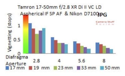
This particular lens has electronic aperture, hence it opens every time you detach it from the body. But I found a workaround you can try at your own risk. I have a speedbooster for it. I have set the camera to "hold exposure mode" (exposure is as long as I hold the shutter), while holding it I detached the lens from speedbooster and it worked and my camera survived it.
Other lens behavior except vignetting should not affect us. I heard the CRI of the led should pass through it, maybe only unnoticably shifted in temperature. But I am not a lens expert. Anyways this lens has actually quite good rendering for its low price, I just do not like the handling - focus ring is only 30 degrees or so and AF is unusable.
- Relay lenses
This lens pair will resize the light leaving the integrator rod to match the image circle of the zoom lens.
- Integrator rod
Since the LED emmits uneven light in color and intensity, we need to mix it. It is an optical prism whose internal reflections even out the light and at the same time produce rectangular image, so our projection has more effective area.
- Condenser lens
Captures the wide angle light emmited from the LED and reconstructs it to a new beam, which can fit the integrator rod.
- Led
You really need LED, because if the light has infrared spectrum you might burn out your lens. High CRI >97, 6000K+ is advised. My unit is 18W. Also since we will do longer exposure times, it is better to avoid flash.
- Heatsink
To keep the led under 60C, else it doesn't last that long. Maybe you have some lying around from old PC like I do.
- Case
Everything will be inside a metal case. Metal is preffered so it does not change shape when humidity changes. Three legs to prevent wobble. Cushioning to deal with micro vibrations.
No ICC profile disclaimer
Big disclaimer is, I will not use an ICC profile to get correct colors. We will make a profile which behaves the same way with curves - it is advised to have a program which allows macro recording, then it will be a general one step process for each camera, transparency version, LED type, diffuser and projector lens. If you change any of those, you will have to make a new profile. At first this gives us a headache, but it makes us free from IT8 converting softwares.
Most LEDs are not uniformly bright or colored, lets hope our integrator rod solves it.
Step 1: Salvaging a DLP projector
It has all the critical lens elements already perfectly aligned. You can buy old non functioning unit very cheaply, just remember to take out the whole optical system (Aspheric condenser, integrator, relays, zoom lens) in one piece. Maybe you can even use the zoom lens which came with it, but be aware of it's vignetting.